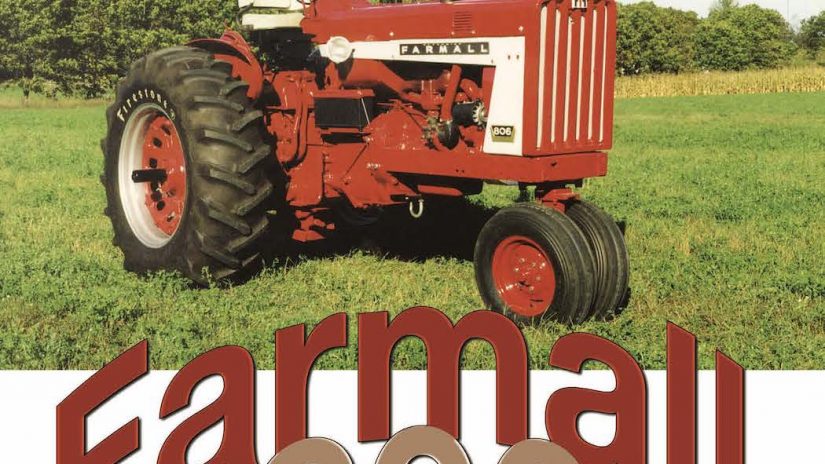
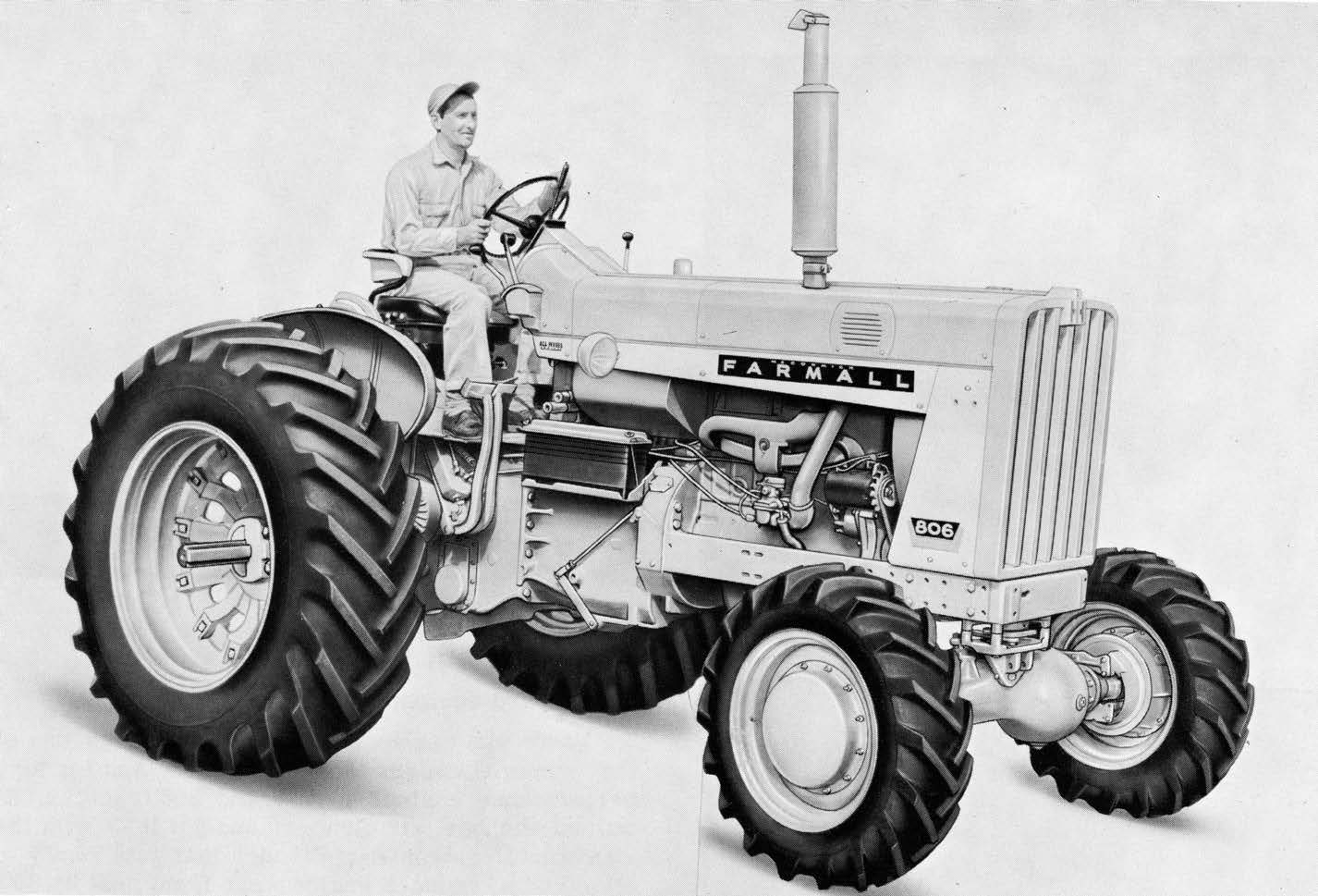
In the year 1963, IH released its first “clean sheet” designed tractor that was engineered at its new Hinsdale, Illinois engineering facility. This was the new model 806 tractor. The 806 was built by IH from 1963 to 1967 and offered in gasoline, diesel and LPG powered versions. The gasoline and LPG versions had an inline six cylinder engine that had 301 cubic inch displacement. The diesel engine was 361 cubic inches in size. These tractors were produced by IH at their Farmall Works factory in Rock Island, Illinois.
The LPG powered tractors were most prevalent in the central plains region of the USA. This was due to the fact that many gas wells were existent in that area and farmers had easy access to the fuel. There were a number of LPG tractor “hot spots” in the Midwest where LPG tractors of all colors were found. A lot of this depended on the dealer in the area of the LP gas supplier.
One IH dealer in Indiana was also the largest LPG tractor dealer in the region because they sold LP gas as a sideline! Of course, they were going to push LPG powered tractors. They wanted your fuel business, too!
One of the positive features of the LPG tractor was that the engines were clean burning. They did not soot up like the diesel or gasoline powered models did as LPG is a much cleaner burning fuel.
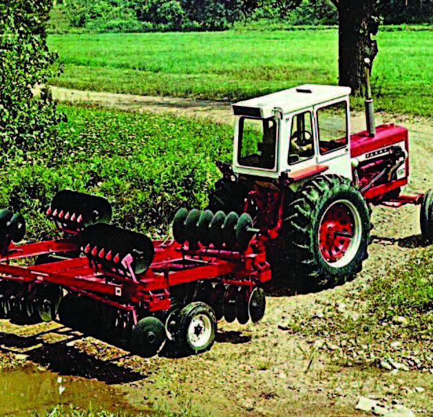
One of the important maintenance items to follow with an IH (or any other brand) gas or LPG powered muscle tractor was to use a low ash engine oil. The oil for a diesel engine and its gas/LPG counterpart were formulated VERY differently! The additive or chemical composition of each was significantly different. Typically, diesel engine oils have a higher sulfated ash content as they NEED this component for lubrication. When higher ash oils are used in a gas/LPG engine, serious damage can occur, like valve torching and valve stem deposits. IH engineering discovered this and they formulated a low sulfated ash content oil called (what else?!) Lo- Ash engine oil. Since Lo-Ash oil had a lower sulfated ash content, longer engine life with fewer issues were part of the benefits derived from using it.
IH used Ensign branded LP gas equipment (regulator, vaporizer, fuel filter, etcetera) on its LPG powered tractors with its own IH built carburetor. The internal components of the gas versus LPG engines were nearly identical.
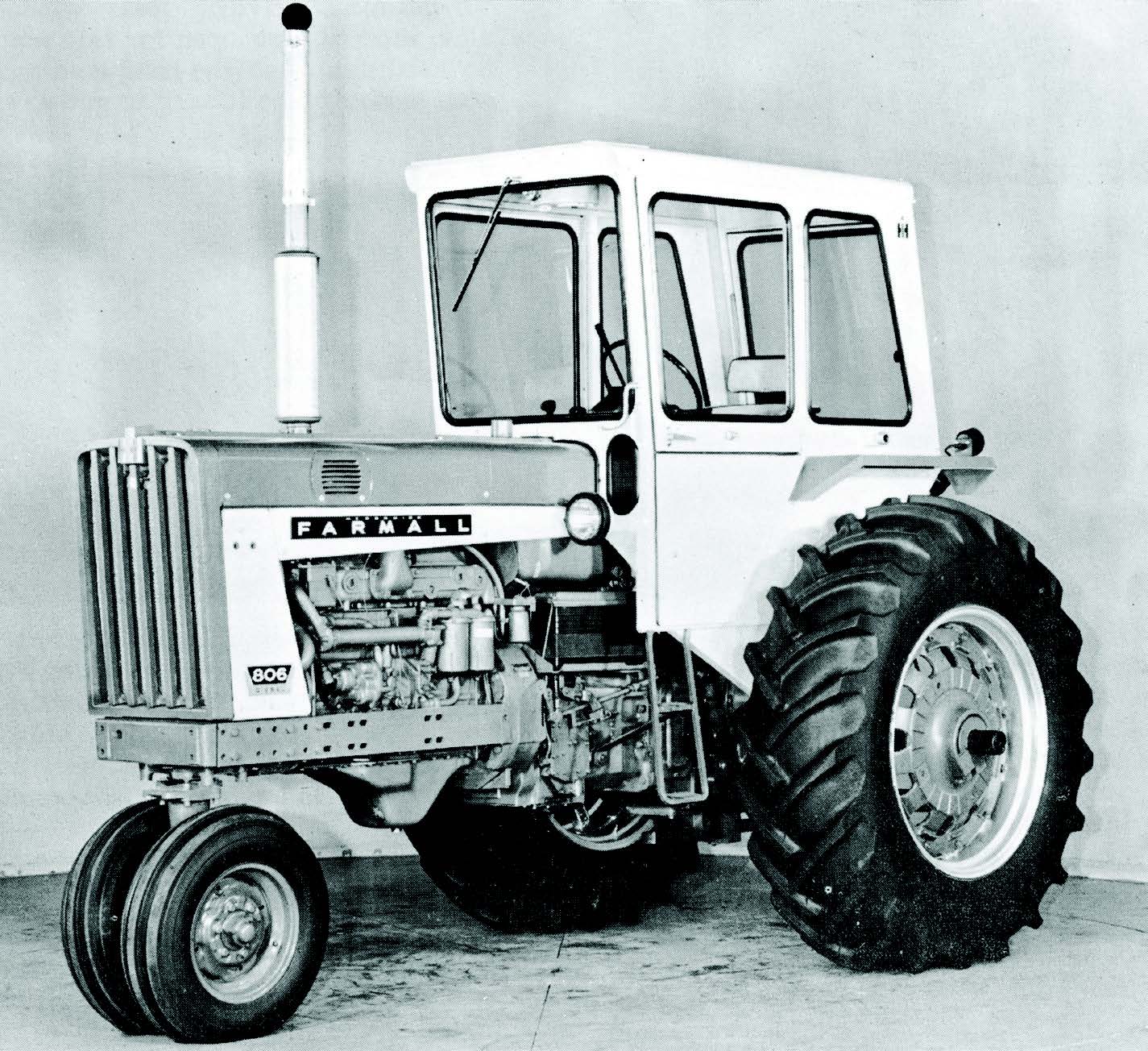
The lubricating engine oil filter on the C-301 gas engine was a cartridge style with a replaceable paper element. Over time, the metal canister that the filter was inside of could get damaged from normal maintenance and wear. IH offered a spin-on filter adapter kit for the C-301 to convert the engine from the paper element (number 323827R) to the spin on (398080R) for easier servicing. The spin on filter setup was much easier to use as there weren’t sealing rings and washers to wear out and leak.
One “issue” IH had with the 806 fitted with gas or LPG engines was that when viewed from the side, there was a wide gap between the top of the engine and the bottom of the hood side line. This created a gap that IH felt was not appropriate. (The diesel engine was a few inches taller, so no gap existed on them.) To fix this “issue,” IH created a taller cast valve cover that filled in the gap and made the engine look bigger!
When IH put a diesel engine in the 806, they got it right! They used their own built D-361 engine, which was an inline six cylinder, dry sleeve, direct injection diesel engine. This engine was 361 cubic inches in size. The early made 806 diesels had IH’s own built RD fuel injection pump. The RD style pump was also used on some industrial equipment IH built. IH built the RD injection pump at their works in Milwaukee, Wisconsin. For reasons not specifically given, IH replaced the use of the RD pump with a Roosa Master injection pump. This author believes it was both a cost savings measure (cheaper to buy a pump than build one) and also that the Milwaukee Works was closing soon. Another factor may be that the RD pump was very INTOLERANT of water in the fuel. It was probably more sensitive than most injection pump systems are.
One unique feature of the RD pump equipped engines was the use of a fuel pressure gauge. This gauge was mounted at the base of the steering tower and it indicated the pressure of the fuel into the injection pump. A drop in fuel pressure gave notice that the fuel filters needed to changed.
Another unique feature on the RD pump engine was the presence of two oil tubes on the right hand side of the engine block. The larger tube was used to refill the engine with fresh oil. The smaller tube held the engine dipstick. If you find a block with both tubes, it has or HAD an IH built RD injection pump on it at one time.
One “guarantee” of the D-361 engine was that if you took care of it (regular oil, filter and antifreeze changes), it would take care of you. This author knows of several 806 diesels that have well over 20K hours on the tach(s) and have “never been touched” in the engine. Very, very, few tractors can make that statement.
Coupled behind the engine was IH’s all new transmission that offered four gears in each of three ranges (high, low and reverse) for a total of eight forward and four reverse speeds. If the tractor was fitted with IH’s all new hydraulically engaged Torque Amplifier (T/A), the number of speeds doubled! The T/A was an optional item that more tractors than not were equipped with.
The T/A acted as a power shift gear reduction unit. When the T/A handle was pulled back, the tractor speed slowed and pulling power increased (T/A drive). Push the handle forward and direct drive was restored. There was no need to touch the clutch pedal to use the T/A. One lever controlled it all.
Initially, IH had planned and tested a turbo 400 automatic transmission to be placed in the housing behind the engine. The housing was designed and cast to specifically fit that unit.
IH engineers had major issues getting the 400 automatic to shift smoothly (modulate) between speeds. This became such an issue through testing that the automatic transmission idea was scrapped and a hydraulically engaged Torque Amplifier took its place. A couple of internal casting changes were made for the T/A, but with very little work, a turbo 400 automatic could be fitted into a current housing.
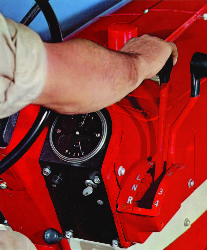
A simple inline shifting control mechanism was featured on the 806. The outer lever controlled the speed gear selection (1 through 4). The inner lever controlled the range transmission (high-low-neutral and reverse). When the tractor’s range lever was placed in neutral, the transmission park lock could be engaged. Here a cast iron pawl engaged the reverse idler gear in the range transmission. The early tractors had a foot lever that engaged this. IH found that this foot lever could be bumped to the “ON” position with the tractor moving, causing massive gear tooth decay/damage. A service bulletin and lever replacement package were developed and a new HAND operated lever was installed. This lever was mounted higher off the platform than the foot pedal, so the chance of accidental engagement was greatly reduced.
IH used Delco-Remy brand components in the electrical system on the 806. The earlier built tractors had a generator with an external regulator. The later made tractors had an alternator with an external regulator. The 806 FWA tractor in the photos has been updated to a Delco style alternator from its original generator.
If you want to restore the tractor to “factory original,” you’ll need to get Prestolite batteries, too. The gas/ LPG tractors used a single 12-volt 3EE size battery, the diesel tractor has two six-volt batteries (3EH size) that were cabled in series to create a 12-volt system. This author has seen (and done) several battery conversions on the diesels to use two of the 3EE 12-volt batteries. These each had their own ground (-) cable and their positive (+) cable go directly to the starter. Since the 3EE and 3EH batteries are similar in size/shape, etcetera, they have the “factory appearance” that is so important when restoring your muscle tractor.
At the rear of the tractor, a dual shaft/dual speed (540-1000 RPM) independent PTO was hydraulically actuated by a lever near the right rear corner of the seat. The early built tractors had a cast handle, the later built units had a formed steel rod. The PTO had its own hydraulic pump that supplied pressurized oil to the multi disc PTO clutch stack.
On the original, factory built PTO units, IH used a series of fiber lined clutch plates with steel separator plates. There were 12 steel plates and five fiber plates. IH engineers upgraded the PTO unit in their tractors that were built in the 1970s’ era to have a heavy duty clutch stack. This was comprised of seven fiber plates and nine steel plates. Whenever you rebuild an IH PTO unit like this, ALWAYS install the heavy duty (7 and 9) clutch plate setup. ALWAYS replace ALL of the seals, sealing rings and gaskets, too!
The 806 could be fitted with IH’s Fast Hitch rear hitch or its new threepoint hitch. The three-point hitch quickly grew to fame for its draft sensing system. IH used a lower arm torsion bar sensing system. This used a torsion bar mounted to the lower mounting arm tube of the three-point hitch. The bar interacted with the draft control valve via direct linkage. Competitive brands used complex linkages or springs that were highly inaccurate and could break and wear quickly. The IH torsion bar sensing system measured the draft load many times per second and made an instant correction (if needed) to match the setting selected by the operator.
The transmission and final drive housings also served as the hydraulic oil reservoir. A single replaceable cartridge filter with bypass valve kept the oil clean. Mounted ahead of the tractors radiator was the hydraulic oil cooler. This could be accessed by removing the tractor’s grille (no tools needed to do this) and it could then be cleaned.
Mounted in the speed transmission housing (housing directly behind the engine) was the MCV pump. The MCV pump supplied hydraulic oil to the T/A (if equipped) power steering and power brakes. This pump was driven by the IPTO drive gear, which was coupled to the engine. In the event that the MCV pump failed, the steering and brake functions would still operate but at a lesser volume. This was a safety feature to keep the tractor from “locking up” when moving and thus creating a serious accident.
IH offered up to two remote hydraulic valves. These valves were located under the seat and could be repaired without removing the seat, too. The valves delivered hydraulic oil via steel lines to the couplers in the rear of the tractor or (using steel lines) to the center steering column outlets. The center mounted outlets were especially helpful if you had a front mounted cultivator or front mounted loader. One drawback on the “dual outlet” hydraulic system was that if you had something plugged into the rear outlets AND the center outlets, they would BOTH be live when the control lever was moved!
A wide, flat operator’s platform was provided and vertical acting seat with a mechanical seat suspension was standard equipment. The seat had three positions—fully down, fully up or partially up. This let you adjust the seat to the size of operator. A single handle adjustment for the operator weight also let you “fine tune” the comfort for the operator. For some operations (corn picking), the operator could raise the seat up and back out of the way to give plenty of room to stand on the platform.
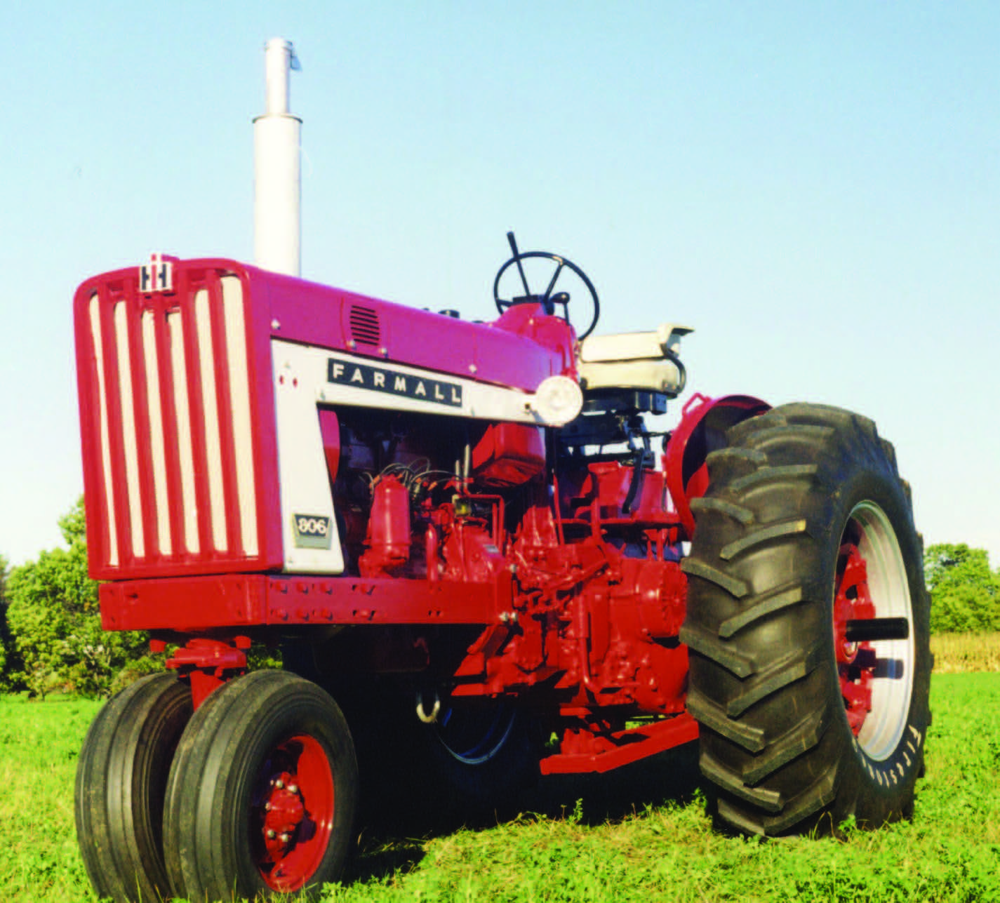
Twenty-plus years ago, this author had the great pleasure/honor to own a Farmall 806. It was a narrow front gas engine with an IH Fast Hitch. I restored it to a near factory original state using correct IH hood bolts, decals and even the foot operated park lock lever. It was good to know that piece of IH history was saved.
The 806 tractor was a major model in IH’s lineup in the 1960s with nearly 43,000 of them being produced from 1963 to 1967. Many of them were used in tractor pulling, plowing contests and such. The 806’s durability and reliability were hallmarks for IH and they set the stage for IH’s future tractors to build upon.
